
In my previous article I explained some steps useful for my Little Experiment with my Raspy.
Yes, I gave it a name, I’m stupid and geek ;)
This time I’ll explain my first usage of Golo to control the GPIO of my Raspy.
If you didn’t prepared your Raspy for Golo usage, just follow my article.
All those previous articles looks like I prepared something ? ;)
When you have the hardware and software ready, we can jump on the next step: light a LED! ;)
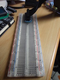
First, connect the cobbler breakout to the Raspy and the breadboard.
It will allow multiple future experiments without more soldering.

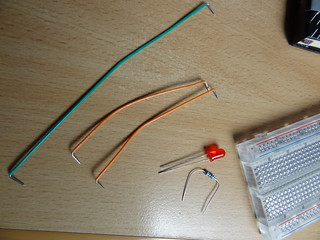
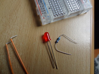
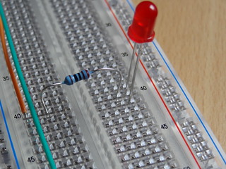
Prepare a LED. I chose a red one, some K2000 reminiscence ;)
The resistor is here to limit the current allowed through the LED.
If you want further explanation on this, you can read Gordons projects page or the Pi4J corresponding page.
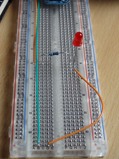
Start by pinning an orange cable to pin marked #18. It is the GPIO1 pin.
Use then a green cable to pin the GND pin.
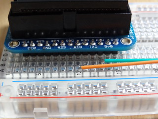
Put a resistor and then a LED:
Don’t forget to close the circuit:
From now, you have everything to run the first sample from the Pi4J project.
First, follow their instructions to download and setup the library
Check that the control sample in Java is working.
If you saw the LED switching on and off, you’re just one step ahead of this article goal.
You have the hardware, you have the Java sofware.
But wait… where’s the Golo software ? :)
Oh, look! Here!
module PiG.gpio.control

# adapted from http:#pi4j.com/example/control.html
# which is
# Copyright (C) 2012 - 2013 Pi4J
# Licensed under the Apache License, Version 2.0 (the "License")
#
# Golo version by Thierry Chantier
# Copyright (C) 2013 Pi4J
# Licensed under the Apache License, Version 2.0 (the "License")

import com.pi4j.io.gpio.GpioController
import com.pi4j.io.gpio.GpioFactory
import com.pi4j.io.gpio.GpioPinDigitalOutput
import com.pi4j.io.gpio.PinState
import com.pi4j.io.gpio.RaspiPin

import java.lang.Thread

#
# This example code demonstrates how to perform simple state
# control of a GPIO pin on the Raspberry Pi.
#
# @author Robert Savage (original java version)
# @author Thierry Chantier (Golo-lang version)
#

function main = |args| {

        println("<--Pi4J--> GPIO Control Example ... started.")

        # create gpio controller
        let gpioInstance = GpioFactory.getInstance()

        # provision gpio pin #01 as an output pin and turn on
        let pin = gpioInstance: provisionDigitalOutputPin(RaspiPin.GPIO_01(), "MyLED", PinState.HIGH())
        println("--> GPIO state should be: ON")

        Thread.sleep(15000_L)

        # turn off gpio pin #01
        pin: low()
        println("--> GPIO state should be: OFF")

        Thread.sleep(1000_L)

        # toggle the current state of gpio pin #01 (should turn on)
        pin: toggle()
        println("--> GPIO state should be: ON")

        Thread.sleep(15000_L)

        # toggle the current state of gpio pin #01  (should turn off)
        pin: toggle()
        println("--> GPIO state should be: OFF")

        Thread.sleep(5000_L)

        # turn on gpio pin #01 for 1 second and then off
        println("--> GPIO state should be: ON for only 1 second")
        # set second argument to 'true' use a blocking call
        let duration = 1000_L
        pin: pulse(duration: longValue(), true)

        # stop all GPIO activity/threads by shutting down the GPIO controller
        # (this method will forcefully shutdown all GPIO monitoring threads and scheduled tasks)
        gpioInstance: shutdown()
}
My project is now going well. I’m starting to convert to Golo every sample from Pi4J and give them back as a contribution.
I hoped to have enough time to show a full video of all the process, but it was quicker to do this article.
If you have any question, feel free to comment or to drop me an email.
Comments powered by Talkyard.